Installing a gas boiler will help to solve the problem of heating, warm water and optimizing the internal microclimate in housing at its discretion. But in order to avoid breakdowns and mitigate the risk of gas fire, installation and further operation of such a powerful electrical appliance must be carried out in compliance with all rules. Do you agree?
We will tell you how to make grounding for a gas boiler in accordance with building codes and recommendations of the PUE. In the article we proposed, the installation technology is examined in detail. Our advice on choosing a material and performing preliminary calculations will allow you to perfectly ground the equipment.
Why do you need to ground the gas boiler?
A mandatory element of the device of any gas boiler is a metal casing, on the surface of which static charges are formed when the device is connected to the network.
And if you do not take care of the “waste routes” for electricity, at one unfavorable moment, the entire electronic component of the device or its individual elements may fail. For example, a board or control system.
To prevent this, the boiler is “insured” by grounding - a conductor that connects the appliance to the ground electrode, and the latter - directly to the ground. The earth has the property of "absorbing" electric current, so its environment will be a guarantee of safety from equipment failure in case of voltage drops or short circuits in the network.

Whatever type of boiler you choose - gas, solid fuel, electric - the correct installation of equipment is impossible without arranging the ground loop
Grounding is necessary so that:
- Reduce the explosion hazard of the device - Static electricity often causes spontaneous combustion of gas-powered devices, and even under pressure.
- Eliminate the probability of injury - the metal case sometimes “breaks through”, and when touched, a person can feel an electric shock from a slight tingling to a powerful charge, followed by death.
- Prevent damage to automation - gas boiler boards are sensitive to voltage surges, and their replacement will cost at least a third of the cost of the equipment itself.
In addition, there will be a lot of questions from the gas service inspectors for a boiler that works without grounding, which can lead to significant fines and forced shutdown of the device. Therefore, it is worthwhile to equip the grounding circuit in any case, because this is not only about economic nuances, but also about your safety.
Image Gallery
Photo from
Grounding is mandatory for all types of volatile gas boilers - floor and wall models, in the design of which there are devices powered by electricity
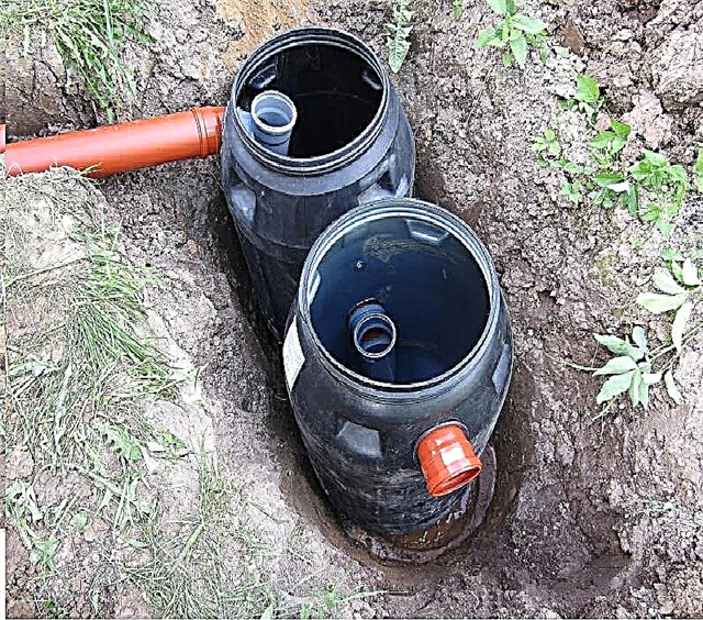
It is not allowed to ground gas equipment on pipes of heating and water supply circuits. The grounding system needs to be moved outside the house
In the event of a breakdown of the electric charge on the case arising in the event of a wire insulation violation, grounding provides current drainage along the simplest path, protecting equipment and home owners from shock
The grounding system, designed to equip a gas boiler, removes the static, preventing failure of the sensor readings and disturbances in the operation of the electronic board
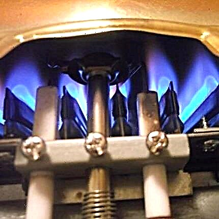
The static field arising during the operation of the gas boiler can affect the operation of the solenoid valve, as a result of which the equipment will not ignite and gas will not be able to enter the burner
The ground wire from the gas boiler is led outside and connected to a ground system immersed in the ground. Charge pierced to the housing must be discharged into the ground loop.
Despite the fact that the tolerance limit of the PUE for resistance to the boiler is 30 Ohms, gas workers recommend sticking to 10 Ohms, as the soil in the upper layers is mostly clay (sandy loam, loam)
The internal ground loop can be connected to the outside through a bus mounted in a separate box or through a common house ground bus located in a common panel
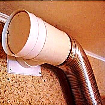
Floor model of a gas boiler
Grounding out of the house
The purpose of the grounding system for a gas boiler
Sensor and electronic board protection
Gas boiler solenoid valve
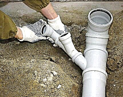
Grounding system outlet
Measurement of grounding resistance for the boiler
Ground connection in a separate box
Subtleties of the circuit device
The grounding system may be natural or artificial. The first option includes structures made of metal or reinforced concrete, which are in direct contact with the ground. It can be the foundation of a building, a pipeline or other underground utilities.
But for a gas boiler, natural grounding provides for the presence of at least two contacts with separate parts of the housing, and the sewerage, heating and gas pipes in this case are excluded. Therefore, during installation, an artificial system is often used, the organization of which we will consider.
What material to choose for grounding?
For artificial grounding, rods or pipes that are interconnected by metal strips become conductive electrodes. They are installed vertically in the soil in order to ensure the operation of the system even in the winter season, when the top layer of soil freezes.
An important condition is that metal elements must not be protected from corrosion by an insulating material.

The service life of the ground loop largely depends on the availability of corrosion protection on its electrodes - copper-clad and stainless elements will last the longest
On sale you can find ready-made kits for the grounding system, which consist of steel rods (usually with a copper coating) and special pointed tips for soil of various densities.
The kit also includes anti-corrosion agent for processing the system before installation and connecting elements - brass couplings, clamps. The main advantage of such a solution is that it is possible to assemble the circuit without welding work and lengthy preparation.

Although the controlling services advocate ready-made kits for grounding, it is feasible to make the design yourself - this will not be a violation, but it will cost several times cheaper
To assemble a system from improvised materials, several important nuances should be taken into account:
- Metal structures intended for installation in the ground can be made of a profile pipe, an I-beam, a channel, a corner.
- The grounding metal must be protected from destruction by galvanizing, copper plating or, in extreme cases, anti-corrosion paste.
- The cross-sectional area of the wire connecting the zero phase of the shield to the ground loop depends on the type of metal from which it is made. The optimal value for copper is 1 cm2, for steel - 7.5 cm2, and for aluminum - 16 cm2.
- The grounding resistance for sandy soil should not exceed 50 Ohms, for clay soil - maximum 10 Ohms.
- Materials for the electrodes must be selected and taking into account the resistance of the circuit. The best option is two-inch pipes or corners with a length of 2 m and a cross-sectional area of 5 cm2.
- The grounding bar is made of copper or steel strip (aluminum is prohibited for this case).
Compliance with these requirements and the correct installation of the grounding loop will help to eliminate claims from gas inspectors, regardless of whether you used the finished modular system or assembled it yourself.
Image Gallery
Photo from
Stainless Steel Ground Loop
Using Conductive Graphite Lubricant
Serial ground circuit device
Tinned copper grounding busbar
Calculation of circuit parameters
The list of requirements for grounding includes several indicators, the algorithm for obtaining which may not be clear to a novice in the business of electricians - for example, how many electrodes are required for the correct operation of the system or how to measure the loop resistance. Let's try to clarify the basic principles for determining these parameters.

Find out the resistivity of the soil, grounding devices of any configuration and even the presence of communication between the electrodes using a special meter
Grounding is done after installing a gas boiler in a country house. The physical parameters of the ground loop are selected mainly empirically. This practical method is suitable for those who are afraid to get caught up in complex theoretical calculations.
The execution algorithm is as follows:
- We take as a basis a contour in the form of an isosceles triangle of three metal rods 3 meters long.
- We connect the conductors.
- We take an ohmmeter (a device for measuring resistance) and measure the performance for the circuit. The ideal value is 4 ohms.
- If the result obtained significantly exceeds the optimal indicator, we add one more element to the circuit and check the resistance again. We continue until we get the ideal indicator or at least the maximum allowable value for the boiler circuit of 10 ohms.
But you can determine the required number of electrodes with the help of formulas, choosing suitable options for your case.

Using this formula, it is possible to determine the resistance for one electrode, if in the area where the house is located, the soil is homogeneous, and does not lie in layers
In the formula, you need to substitute the average value of the resistivity, depending on the type of soil in which the ground electrode will be located:
- wet sand - 500 Ohm * m;
- solid sandy loam - 300 Ohm * m;
- clay-sand mixture - 150 Ohm * m;
- loam - 100 Ohm * m;
- semi-solid clay and chernozem - 60 Ohm * m;
- garden land - 40 Ohm * m;
- refractory loam - 30 Ohm * m;
- peat - 25 Ohm * m;
- plastic clay and salt marsh - 20 Ohm * m.
The least suitable for the installation of the grounding circuit is stone and rocky soil. In this case, an artificial embankment will have to be erected.

For heterogeneous soil, it will be more difficult to calculate the resistance for one electrode, but this can also be done by substituting your data in the specified formula
The seasonal climatic coefficient of soil resistance depends on the area where your home is located. They are conditionally divided into 4 groups.

Correction for climatic features is especially important for areas with cold winters, since grounding efficiency is significantly reduced in frozen ground
There are also more complex algorithms for accurately determining the parameters of the electrodes and even special programs for their calculations. But for the correct operation of the gas boiler, it will be enough to follow the general recommendations for arranging a standard ground loop.
The use of copper-bonded steel grounding conductors allows you to build systems in soils with any physical and mechanical properties:
Image Gallery
Photo from
Copper Steel Earthing Kit
Vertical earthing packaging
Installation in the ground with a jackhammer
Innovation - the use of electrically conductive composition
Installation of a grounding system for the boiler
To install the circuit, you need to allocate free space, which is located at a distance no closer than one, but no further than 5 meters from the house foundation.
This site can not be used in the future for the construction of various extensions, landing work, and indeed a person is not safe to be on it, because if it is triggered it can be fatal. Therefore, it is worth fencing the contour with a border and ennoble the place with some composition of stone or decorate it with a garden sculpture.
Design and preparatory work
To ground the gas boiler, first a mock-up of the future circuit is drawn on the selected area. Most often, a scheme is used that involves the placement of grounding conductors on the sides of an isosceles triangle.
But the contour can also be in the form of a line, square or polygon - it all depends on the estimated number of electrodes and the location of the building itself.

Although traditionally, when arranging the contour, an isosceles triangle with sides of 0.5-2.5 m is chosen, with a deficit of free space near the house, the system can be linear
To assemble a home-made design, you will need such tools:
- a welding machine for connecting metal elements of the system;
- grinder for cutting and sharpening pipes or rods;
- puncher or drill for the plant grounding cable in the house.
And you also need to prepare a digging tool. The minimum set, which probably will be in stock at the owners of a private house - a bayonet shovel and a heavy sledgehammer. But if the site is hard soil, it is better to get a Yamobur or Motobur, which will greatly facilitate the "deep" stage of work.
Installation and connection of the circuit
Now we will consider step by step how to make a triangular contour for grounding a gas boiler. First you need to dig trenches along the lines of a previously drawn layout. The optimal width of each groove is 35–40 cm, and the depth is 50–70 cm. A straight trench is drawn from the nearest triangle top to the foundation.

The triangular circuit is simple and reliable, because even if the metal bridge between the rods is damaged, it will continue to function on the other side.
With the help of a sledgehammer or a punch, the electrodes — steel conductors from pipes or corners — are vertically hammered along the vertices of the triangle. To facilitate this process, you can pre-grind the grinder the lower edge of each segment.
They must be installed at such a depth that the distance from the bottom of the trench to the upper edge of the conductor is within 15-20 cm (that is, the entire structure will subsequently be covered with a 30-55 cm soil layer).
Further, the electrodes must be interconnected. Lay along the trenches dug on the sides of the triangle a steel conductor with a cross section of 4.8-5 cm2 or a strip of width 4 cm and a thickness of at least 4 mm.
The entire grounding loop procedure involves a number of standard steps:
Image Gallery
Photo from
Step 1: Trench for ground loop device
Step 2: Installing the Vertical Earthing Switch
Step 3: Fixing the Horizontal Conductor
Step 4: Mounting the tap to the ground bus
Ready-made grounding kits can be connected with the bolts provided in the kit. And for home-made designs, the best solution is spot welding.

A clear diagram of the grounding device for a gas boiler, for the manufacture of which steel strips and three electrodes were used
Then you need to weld a horizontal metal strip to the steel conductor, which will be led out of the trench to the planned place for the grounding to enter the building itself. It rises above the blind area by about 50 cm (you can use a steel pin).
Now you need to make grounding in the house. To do this, using a punch in the wall, a hole is made through which a copper wire is passed. An M8 bolt is welded to the strip. The copper wire is fixed at one end to the terminal on the ground bus, and the other to the metal plate on the base.

Connection scheme through a three-wire wire to the circuit and the pole of the power transmission line (for the organization of such a connection, it is necessary to obtain permission from local power networks)
Then the gas boiler is connected to the shield through an individual circuit breaker using a three-wire cable. Additionally, it is recommended to install a voltage stabilizer.
How to check the operation and get a grounding certificate?
Using a measuring device, find out the current spreading resistance along the circuit. If the result of measuring the grounding resistance does not exceed the maximum allowable figure of 10 ohms, then you can dig trenches.
If deviations are found, add the required number of electrodes, make sure that the resistance is normal. The grounding is ready, you can dig in the circuit and call the inspection.

To dig trenches with grounding conductors, use only homogeneous soil, without admixture of stones and construction debris, and close the place of entry of the system into the house from rain with a PVC box
By the way, there is another way to check the health of the system. To do this, you need a simple light bulb with a power of 100 W (or more), which is screwed into a carrying cartridge. Then one end of the carrier is connected to one of the horizontal strips of steel installed on the sides of the grounding triangle, and the second to the phase of 220 volts.
Compare the result:
- The lamp burns brightly, as if plugged into a power outlet - the circuit is working.
- The lamp is on, but the light is dim or blinking - boil again the joints of the structure.
- The lamp is off - you need to check the integrity of the entire circuit, from the quality of welding to the connection to the shield.
Representatives of regulatory authorities are usually guided in checking the readiness of equipment for operation by the recommendations of the PUE specified in paragraphs 1.7-1.8. They determine the resistance of the soil and the ground loop, the correct connection to the shield of the gas boiler and other parameters.

Without the act and protocol, inspections from the gas service may refuse to connect your home to the gas main
If all indicators are normal, a grounding certificate is issued. It is a set of technical documentation from the test report indicating the list of used measuring instruments, laboratory registration certificate, protocol for checking the circuit between the ground loop and the boiler, and a defective sheet.
The following article, which we recommend reading, will familiarize you with the features of grounding the bathtub in an apartment in a multi-story building.
And finally, we offer a selection of video materials where you can get a visual representation of how to safely ground a gas boiler in a private house.
In this video you can see the construction of the grounding circuit of 4 rods with the task of achieving a resistance of up to 7 Ohms:
Another option for arranging the gas boiler circuit for a private house connected from a pole:
The grounding system is an important step that should not be neglected when installing a gas boiler. And if you are not sure that you can correctly install and connect the circuit to the shield, it is better not to risk it and turn to the builders, because not only the safety of expensive equipment is at stake, but the most important thing is your safety and even life.
Tell us about how you built the grounding system in your suburban area. It is possible that you have information that will be useful to future independent installers of grounding systems. Please write comments, post photos on the topic and ask questions in the block below.