Electrical panels located on the stairwells of apartment buildings are controlled by electricians from the management company. However, you must admit that every home master is obliged to know the purpose of the electrical devices enclosed in a metal box.
We suggest figuring out how to install a circuit breaker if an urgent need arises. We will tell you how the machine is arranged and give recommendations for choosing an electromechanical device.
This knowledge will help you to replace the device yourself and take measures in an emergency when the machine has worked.
Why knowledge of electrics is necessary
Information on electrical devices known from school physics lessons is not enough for practical use.
An ordinary consumer is more likely to encounter circuit breakers, since they are the ones that operate in connection with network congestion. It is not enough just to return the lever to its usual position, it is necessary to understand the reasons for the shutdown, otherwise the situation may repeat itself in the near future.

To navigate the stuffing of the electrical panel (which, by the way, is a mandatory element of the power system of private houses), you need to know the composition and purpose of all devices - pulse relays, load switches, RCDs, etc.
Do I need to be able to independently change the automation? We recommend that you first study the theory, and at the first shutdown - and practice.
The fact is that there is not always the possibility of quick help from professionals: on a day off, electricians rest on an equal footing with the rest. And if the house is located in a country house or in a village, it is better to get acquainted with the electricity network and related devices thoroughly.
Design and purpose of the machine
Despite the name - “automatic”, this type of circuit breaker operates only in one direction - it opens the electric circuit (if the rating is exceeded or the overload associated with the simultaneous inclusion of several powerful electrical appliances). Turning on, that is, closing the circuit, is possible only in the only way - manually.
Unlike a simple single-key switch, an automatic device has a more complex device. Schematically, the classic version (without an electronic unit) is as follows.

The terminals are located at the top and bottom, with the top connected to a fixed contact, and the bottom closely connected to the metal plate, which plays the role of a thermal release. When the temperature of the material rises, the plate deforms (+)
There are several ways to start the trip process:
- manual control - on / off with the help of a small lever;
- current impact short circuit;
- overload - excess of rated current parameters.
In order to prevent a powerful thermal effect from burning the switch, an arcing chamber (a set of insulated copper plates) is provided, which cools and breaks the electric arc.
Electromechanical device selection
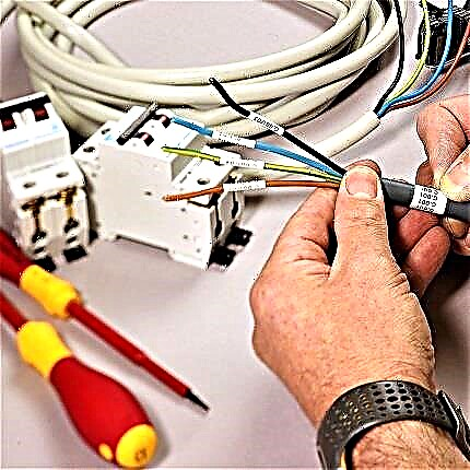
Given the load parameters and cable characteristics, you can choose a device for installation in an electrical panel. All the necessary information about the electromechanical device is located on its front panel.
The ability to decipher the marking of the switch will help make the right choice.

The first line usually indicates the brand of the product. It’s better not to save, but to choose an automatic device of a well-known manufacturer: Legrand, IEK, ABB, Schneider, Electric, Hager (+)
Voltage, frequency and rated current
In the next line, you can find information about two important characteristics - voltage and frequency. The most common “format” is 220 / 400V 50Hz. This means that you can connect both one and three phases at a frequency of 50Hz.
If we take all the structural types, then the correspondence of the poles and voltage will be as follows:
- 1 pole - 220 V, (1 wire - phase);
- 2 pole - 220 V (2 wires - phase / zero);
- 3 pole - 380 V (3 wires - phases);
- 4 pole - 380 V (3 phases / 1 zero).
The value of the rated current limits the use of certain types of cables - and this must be taken into account when choosing automation. Therefore, when buying a switch for an electrical panel, check what types of wires are involved in building the overall circuit.
A preliminary calculation of the circuit breaker rating is based on data on the total power of consumers, the presence of inrush current of some electrical appliances, current strength and the estimated demand factor.
In no case do not build on the maximum voltage in the network, otherwise the following may happen.
Suppose the purchase of new household appliances leads to overload and constant knocking out of the machine. You will want to increase its power and replace it with a new one with a higher rated current.
As a result, when several powerful devices are connected to the network, the machine will not work, but the wires will overheat, resulting in a short circuit (insulation will melt, fire will occur).

If the cable cross-section does not correspond to the load, it must be reduced (or, conversely, updated communications). But you can not pick up a circuit breaker, focusing on the maximum load - only by cable (+)
The circuit should be built in such a way that the weakest link is precisely the circuit breaker (and not the wires), which is designed to protect against overload.
Is BTX important
The letter designation of the time-current characteristic is preceded by a digital marking that defines the rated current.
To understand what the essence of BTX is, let's analyze the formula:
k = l / lnwhere
- l - current in the network;
- ln - rated current value;
- k - multiplicity.
The category depends on the multiplicity:
- B - 3
- C - 5
- D - 10
- C - 5
The compliance graph is clearly shown in the figure:

Three zones, painted in different shades, indicate BTX categories: red - category B, blue - category C, green - category D (+)
The response speed of the machine depends entirely on the multiplicity: the larger it is, the faster it will turn off. For domestic use, the listed categories are used, but in addition to them, you can find circuit breakers with BTX categories G, K, L, Z.
The circuit breaker B16 at a current of 150 A works instantly, while D16 - only after heating the plate, after a few minutes. The most common category C is used in everyday life and in production, in networks with medium and low starting currents. Category B refers to high-speed, participates in the schemes of old networks.
Keep in mind that the ambient temperature also affects the response speed. The dependence is as follows: the higher the temperature indicator, the lower the current required for the response of the machine.
Experienced electricians when assembling electrical panels take into account this correspondence and try to leave a little free space inside the panel so that overheating does not occur due to the operation of a large number of devices.
Do not forget about the selectivity rule: of all the protective devices introduced into the circuit, the one closest to the place of overload should be the first to fire. If the near automaton did not respond, but the next one worked (for example, the driveway), the device parameters were chosen incorrectly.
Pole, PKS and current limit class
The number of poles for modern circuit breakers can vary from 1 to 4, with 1- and 2-pole devices serving single-phase circuits, and 3- and 4-pole ones serving three-phase ones.
PKS is the ultimate (rated) switching (disconnecting) ability. Its indicator indicates the value of the maximum short circuit current (TKZ) at which the machine can still work.
TKZ parameters should not exceed PKS, otherwise the protection guarantee is canceled. If the automatic device has provided protection against TKZ several times, its resource is most likely exhausted and replacement is required.

In everyday life, devices with a PKS of 4.5 kA are most often used, however, there are modifications of 6 kA and 10 kA. The latter are relevant for industrial use (+)
And the last characteristic is the current limiting class. The label can indicate class 1, 2 or 3, in some cases this indicator is not present. If it is not, the device belongs to the 1st class of current limitation. Each class denotes a specific reaction rate of the automaton to the occurrence of TKZ.
Quality and cost depend on the class, as the higher the indicator, the more expensive the device.
The duration of the machines is approximately the following:
- 3rd grade - 3 ms;
- 2nd grade - 5 (6) ms;
- 1 class - about 10 ms.
Most modern switches belong to the 3rd class.
After you select the appropriate circuit breaker, you can begin to install or replace it.

Each element is a module, which occupies the number of places equal to the number of poles (in the figure - samples are unipolar, i.e. 1 place). The size of one "cell" is 1.75 cm, two - 3.5 cm, etc. Additional information on the selection of switches and the characteristics of different models is presented in this article.
Replacing the circuit breaker in the shield
If you open the cover of the electrical panel, you will see that all the modules are fixed on a metal strip called a DIN rail. The width of the plate is 3.5 cm, each module takes 1.75 cm.
Image Gallery
Photo from
Circuit breaker group in the panel
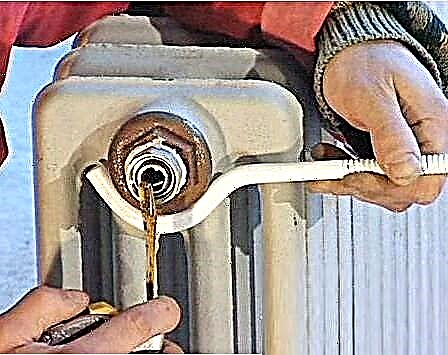
Voltage test with an indicator screwdriver
Dismantling the comb common for all automatic machines
Release from bottom fixation
Fixing fixture if necessary
Preparing to remove a damaged device
Removing a damaged machine from a group
Cleared space for installing a new machine
To install, you need the following tool:
- pliers;
- screwdrivers - cruciform and straight;
- cable cutting tools, such as wire cutters;
- indicator screwdriver;
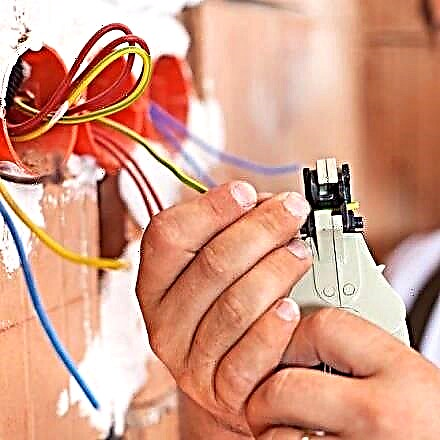
- stripper to remove insulation;
- crimper for multi-core cable only.
The first thing that you must always do before any manipulations in the electrical panel is to turn off the power and make sure that no one accidentally connects the power during operation. For safety reasons, use an indicator screwdriver and check for voltage.
Next, take a pre-purchased circuit breaker and attach it to the DIN rail so that it aligns with similar devices. If there is free space at the edges, then it is better to fix the module with special stops - metal brackets on the screws.

Installation does not require special fasteners, since the latch is located directly on the device’s body, just lean it against the rail and press a little. To remove the failed device, the latch will have to be loosened with a screwdriver
Connecting elements with several poles has differences:
- 2 pole - the left side: top - phase, bottom - phase of the chain; right side: top and bottom - zero;
- 3 pole - the upper parts are the phases in order, the lower parts are the phases of the chain in the corresponding order;
- 4 pole - as 3-pole, but the rightmost module is zero.
As you can see, the main connection principle is that the input is connected to the upper terminals, the output to the lower. Wires are usually routed to the shield. For ease of use, they are grouped with screeds.

It is important to correctly distribute the cable connections. For single-pole devices: the phase coming from the RCD or the input device is connected to the upper terminal, the phase of the circuit to the lower (+)
Having stretched the ends of the wires to the corresponding terminals, arrange them freely, without tension, and remove the excess with wire cutters. With a construction knife or stripper, remove part of the insulation - the length of the bare wire is about 1 cm.
If you use an improvised tool, try not to damage the cable in the transverse direction, so as not to provoke a crease.

Stretching the wires in the shield, try not to bend them, do not make as many turns and creases as possible, and also do not pull like a string
The phase connection can be equipped with a comb - a special bus with the required number of poles. Instead of combs, homemade jumpers from the PV3 wire are also used.
Two wires cannot be placed in one terminal, so they must be crimped with the tip of the NShVI.

Stranded wires must be crimped - attach the tip of the NShVI. The improvised tool does not fit, it is better to use a special device resembling nippers - a crimper
We insert the prepared wires into specially designed holes.

After the wires are stripped and inserted into the terminals, they must be fixed by carefully tightening the fasteners with a screwdriver
Installation ends with a mandatory system test: apply voltage, connect all devices in the circuit and use an indicator screwdriver to check the presence of voltage in the upper and lower terminals. Instead of a screwdriver, you can use a multimeter.
According to the rules, the device must be marked to indicate its belonging to a specific circuit. A similar marking should be present on the protective cover of the shield.
Image Gallery
Photo from
Installing a new circuit breaker
Connecting comb comb
Lead wire connection
Homemade jumpers instead of comb
Instructions for connecting a bipolar machine
And now let's try to figure out how to connect a two-pole circuit breaker to a 220 V electrical household circuit. This means that there will be 2 wires at the input - phase and zero.
The wire required for connection has 3 conductors with a cross section of 2.5 mm (VVGngP 3 * 2.5), therefore, the maximum permissible continuous current is 25 A.
Work items
We have chosen a two-pole automatic protection device, which is as follows:

We will need four contacts, two of which are in the upper part (incoming), two in the lower (outgoing). The fastening will take place using fixing screws securing the pressure plates
On the surface of the case there is a hint - the connection diagram of the machine.

By marking, we determined that the machine corresponds to the cross-section of wires - C40. This means that a current of 40 A is the limiting response current of the device.
The device is mounted on a metal plate - a DIN rail.

If you look from the back, you can see the latch, with which the machine is fixed in one movement on the DIN rail
We figured out the components, go to the instructions.
Step-by-step photo tutorial on connecting
We turn off the voltage in the network, check its absence with a multimeter. We prepare wires that have double insulation. Three wires of different colors are hidden under a layer of external protection. The color matching is as follows: black - phase, blue - zero, yellow - earth.

We need only 2 wires - phase and zero, the third (ground) will go separately. 1 cm remove insulation and insert the bare ends of the wires into the terminals
On the left there should be a phase, on the right - zero. Please note that some of the insulation does not come in contact - when heated, the cable may melt and cause damage to the device. Carefully tighten the screws and proceed to ground.

To fix the ground, we use a feed-through contact, which is fixed on the DIN rail in the same way as the circuit breaker itself. We insert the third wire and clamp it
The next step is to connect the outgoing wires that are attached to the lower terminals.

Similarly, remove the insulation, insert the ends into the terminals and gently clamp them so as not to damage the device case. Next we fix the ground wire
The connection is complete. It remains to apply voltage, move the control lever to the active position and check the operation.
The machine turned off: what to do
An inexperienced user, in the event of a circuit breaker tripping and turning off the light, is in a hurry to restore the operation of household appliances, so he simply opens the protective cover and turns on the device. However, this is not quite the right decision, it is better to first find out the reason for the shutdown.
The first thing to do is to check the connected household units and devices, paying attention to the appearance of sockets and plugs, the presence or absence of the smell of burnt plastic. Too hot forks should also alert.
One of the common causes is an increase in energy load. If you have a washing machine and microwave, and when the vacuum cleaner is turned on, the protection has tripped, which means that an operational overload has occurred. There is only one solution - to evenly distribute the load, that is, turn on powerful devices in turn.

If only one of the several devices constantly reacts, check the serviceability of all devices related to this circuit (the lamp burns out, a short circuit occurs). The reason may lie in the wiring - in this case, be sure to invite an electrician
If the number of devices has not increased, the load has not changed, and the shutdown has occurred - perhaps the high temperature is to blame. When the temperature norm in the shield increases, the machine can also work.
And the last reason is the exit from the standing of the automatic switch itself. After several reactions to a series of increased currents, TKZ, arc extinction, it becomes unusable, which can be determined by external signs. If the terminals are carbonized or the plastic has melted, the device must be replaced.
The videos provide information that will help you understand the device and the connection of the circuit breaker.
Part 1. How to choose a circuit breaker - we study the theory:
Part 2. Briefing on competent selection of a machine:
Step-by-step assembly process for the electrical panel:
Useful advice from a professional:
As you can see, in order to connect a circuit breaker, it is necessary to choose the right device, follow a certain installation procedure and observe safety measures.
If you doubt your own abilities or cannot find the reason for the permanent shutdowns of the protection, be sure to contact a qualified electrician.
Trying to install a circuit breaker yourself? Or maybe they don’t agree with the stated material, or there were questions on the topic? We are waiting for your comments - the communication block is located below.